A Bit of Background

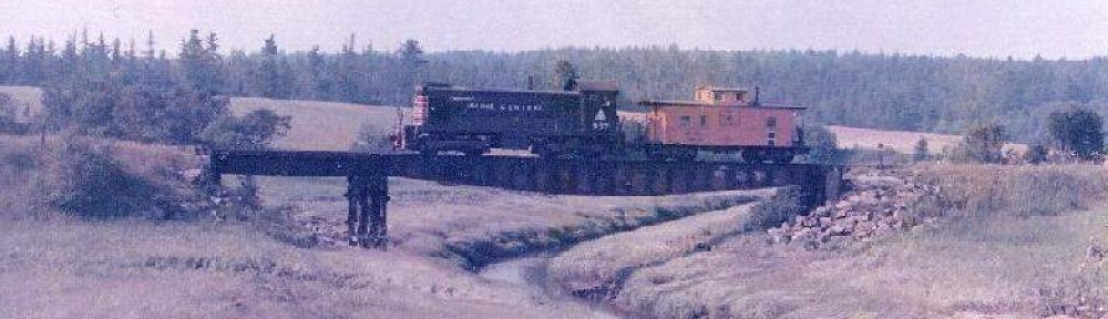
A few new folks have wondered why I picked Eastport Maine to model, so I though I would refresh the story. It all begins with family. My wife’s family are from Maine and New Brunswick, just across the border. When I first started making trips to visit, we found Eastport was about as far as we wanted to travel in one day. It was about an 8 hour ride from our home and just across the border from Canada. I initially picked Eastport as a stopping point over curiosity. For years I had listened to weather reports that covered the coast from ‘Eastport to Block Island, RI’. What I found was a seaport village that seemed stuck in an older time. I also found an old railroad crossing sign. That pushed me into asking questions about the former railroad. What I found is that only a few of the older citizens remembered anything. I began then some historical research. There was plenty about the Eastport fishing industry which at one time was heavily concentrated on sardines. Gradually I learned bits and pieces, until I discovered a friend who was looking into the same history. It turned out that both he and his wife grew up in Eastport and he had railroad memories and she had trucking memories. He played around the railroad as a boy and her family owned the local trucking business. The more I learned and gathered old album photographs, the more I became fascinated with the possibility of modeling the branch. Then an opportunity to move to South Carolina presented itself. That meant taking down my old railroad in Massachusetts of almost fifty years, but a new opportunity to model the Eastport Branch of the Maine Central in O Scale.  Any other scale is out of the question.

As the .design has developed and been integrated into the available space, I have a U-shaped area that has two long sides of 25 feet each and a connector of 15 feet. I have chosen to model four signature scenes which for me will capture the essence of the branch. The four scenes are; Calais, Ayers Junction, Pennamaquan, and Eastport. (Pennamaquan is the river crossing shown at the very bottom of the blog) 

I plan to operate it as a switching road. Original traffic on the line came from and went to connections at Bangor Maine. From Bangor to Calais the line was known as the Calais Branch of the MEC. Trains to and from Bangor carried paper and forest products plus fish related products originating in Eastport. Traffic to and from Eastport connected at Ayers Junction. Therefore the only service Calais provided Eastport was the switching loco, a caboose, and occasionally a snowplow.  Because of how Calais is viewed as a visitor by looking across the yard at St. Stephen, NB, the modeled scene will be the same. In the operational scheme of things this makes Calais backwards, so the awkwardness will be shielded by a view block between Calais and Ayers. Calais will end up more as a diorama although the trackage will be operable. I will use it more as a staging area by pulling cars into and out of Ayers to simulate the arrival and departure of the Bangor train. Eastport had a lot of varied traffic which I will  discuss at a later time when it will become more clear about the role of the harborside industry. Hopefully this will help in your understanding in where I’m going.

Ben


Calais Depot Roof

ImageImageImageToday was a snow day. We got less than 1/2″ but in SC, that’s a big deal. Anyway I stayed home and continued work on the depot roof and prepping ties. The roof itself was built from Task Board which I mentioned previously. It is easy to cut and once glued into a structure it is quite rigid. It has internal ribs to aid the rigidity. I am using laser cut 3 in 1 tab shingles from Rusty Stumps. A bit expensive but this is a foreground model. The shingles are self adhesive, but I also put down a thin bead of ACC to make sure they stay down.

The roof has some odd dormers, two on each long side and one on each end. I made the six out of styrene. The individual window frames were cut from Grandt engine house windows. These dormers when installed will be almost flat and will get a roll roofing treatment. You can see one on the end being test fit.

I also made the chimney using the Task Board and Rusty Stumps self- adhesive brick sheet.

Tomorrow I hope to get back to laying all of the ties that will make up both Calais yard and Ayers Junction.

I would have liked to insert the photos into the text, but so far I haven’t figured it out, so please bear with me as I learn.

Ben


Calais Depot

ImageImageAt home I have been working on Calais depot. This is a rather large brick structure for a small branch, but at one time this was the general offices for the Washington County Railroad, the original builder of the line. Today it has been restored as a chamber of commerce and Indian museum. The restoration work is quite impressive, but of course not as nice as when it was a passenger station.


I had a number of materials to choose from and settled on one called Task Board from Narchitect. It comes in thicknesses from 1/16 to 1/8. The board appears to be a paper type product and is quite stiff, yet easy to cut. Narchitect also makes a lot of different types of molded or vacuum formed styrene including brick. For the brickwork I chose laser etched material from Rusty Stumps. It is laminated to a self adhesive backing which works quite well with the Task Board. To cut out the window and door openings I first laminated the etched brick to the Task Board. Then I marked the brick sheet with a pencil for the guide lines and then cut through both sheets with a #11 Exacto blade. I have previously found that Tichy had the various windows and doors that I needed for the project. The measurements for the openings were taken from the door and window parts.

One problem in making the model is that the prototype brickwork is essentially flush with the wall. To get the header features over the windows and doors would require a lot of custom work, carving the features onto a flat sheet. My compromise is to take some of the Rusty Stumps etched features and laminate them on top of the wall brick. This creates more of a raised effect that the model has over the prototype, but I will live with the accented results.

Assembly and painting are next and then adding the glazing. I am planning to add plenty of bracing inside, although the shell seems quite strong. For adhesives I have been using Tenax for the styrene and my long time favorite GOO for dissimilar materials. Where I need extra strength and longevity, I join surfaces by applying GOO to one surface and ACC to the other. The resulting bond is amazing and stronger than either used separately.

Ben

Ties Are Down

ImageImageSince my last report I completed the roadbed in Calais Yard and now have glued down the ties. It made a huge difference time wise by purchasing ready cut ties and then taping them in strips in a jig The ties are cut from sugar pine and are quite accurate. Spiking should be a breeze, although I’m planning for lots of tedium. A great deal of Calais yard is covered in gravel up over the tie tops. This will reduce the number of tie plates and spikes necessary , a welcome relief. I have done plenty of both in my life and I certainly don’t need to do anything unnecessary.

One of the scenery challenges I’m looking forward to is the duplication of the prototype look. To keep the look in front of me I taped various photos of the yard as a constant reminder.

Ben


More About Doors

Today I started laying out the track center lines and switch templates for Calais yard. I have both Sanborn Insurance maps and plenty of photos. I need to be a bit careful about both. The maps are from a much earlier era when there were a number of railroad served wharves that reached out into the river. Today there is little evidence of those wharves ever having been there.. The photos I have are from several different eras, but there is enough to go on to make a reasonable facsimile of the railroad during the late 70’s.

OLYMPUS DIGITAL CAMERA OLYMPUS DIGITAL CAMERA

The two photos show the current conditions. Calais is shown in the closer view, while Ayers Jct. is visible in the second photo. The next effort will be to start gluing down the Homabed strips. The paper templates shown will be laid on the Homabed blanks and trimmed to shape to fit the centerline layout. Tonight I plan to make a tie jig to space the ties and capture them with tape strips. I also have some lengths of flex track, but I will have to experiment to see if I can back date it to look old and uneven.

Ben

About Those Doors….

A couple of friends have commented about my decision to use hollow core doors as the main base for the layout. The comments center about the choice being somewhat strange. There are several reasons for the choice, not the least of which is remembering what a difficult time I had removing my last railroad which was built quite permanently and integrated into our living space in the basement. This time around I have no basement, but a daughter living near by has a very large one and offered me a section to work in. Her basement is unfinished and there are no plans to change that. I am above average age now and I have decided not to leave her with a mess. By using standard size doors, they can be separated into manageable pieces when the time comes to dismantle.

When planning the railroad I also wanted a structure that was easy to assemble and support. I had heard of some narrow gauge modular groups that were using doors for their ease of use and uniformity. My railroad will be point to point and U-shaped. In some areas I plan to use two doors side by side. The total width is made up from what I need in a particular area. Doors are available in 18″, 24″, 26″, 28″, 30″, 32″, and 36″. All are a standard 80″ long and 1 3/8 thick. I use the type called slabs which are smooth on all sides. They are light weight and easy for me to move as well as strong enough for most of the layout load. For the most part my railroad design is flat and the track will be built right on top of the door. If I need more support in a given area, I just add another piece of wood in the underframe. The doors are constructed with a slender wood frame all around the edges and a honeycomb in between the door surfaces. In those areas where I might have to cut deeper into a door, I will rip some stock to fit in between the panels and repair the edge as needed. Using the doors as the layout base has provided some challenges and later I will describe how I worked around those. I have some photos coming soon which will help to illustrate my methods.

OLYMPUS DIGITAL CAMERA

When it comes to the track, which I have yet to start once it is laid out from the drawings, I plan to use Homabed which is a milled Homosote product and glue that directly to the door surface. On top of the Homabed will be sugar pine ties. Rail will be spiked to the ties and tie plates will be used in the areas where the tie tops are visible. The prototype I am modeling was just prior to abandonment and the track was not in good shape. One of the challenges I’m looking forward to is creating the same decrepit look while still keeping my rolling stock on the rails. Most turnouts will be manually operated and eliminate the need for motors.

My wiring is DCC and I plan to run the two buss wires along the front fascia. Feeder wires from each rail will pass through the door and be brought forward to the front edge for connection. No more under the layout for me.

Once the next two doors are installed, they will answer several remaining concerns as to joining and sizing. I will write more on the subject at that time. In the meantime I’m working on the Calais depot which seems like it has a zillion windows.

Ben

Calais Depot

ImageImageThe depot lies along the edge of the rail yard. Part of it next to the track is three stories high, whereas the opposite street side is only two stories high. This is because it is sited on a ridge. To help illustrate I will add a photo. Note that this is from an earlier era, but does give a nice side view perspective.

I am also including a rear view which is the full trackside or east side. Sorry about the lighting but it was the best we could do the day we were there. The main purpose in taking this photo was to be able to scale it for modeling. As in an earlier photo, my bride is holding a measuring stick which is six feet long and marked in alternate colors every foot. Note that the track is now gone in favor of a waterfront park and walking trail.

The layout is being constructed with a ridge along the front edge. The depot sits on this ridge. The yard will be between 16 and 20 scale feet lower than the ridge and therefore the view will look down a bit on the yard. Along the back of the yard will be the St. Croix River which is a tidal river dividing Calais from St. Stephen, New Brunswick. I have allowed roughly a foot of depression between the yard and the wall to provide space to simulate the river. The wall will contain a photo mural of St. Stephen to obtain the overall perspective. The frontal ridge wraps around the end of the layout to the left and carries the road across the bridge to Canada. The right hand end of the scene will end in a curved wall which will serve as a scene divider between Calais and the next modeled scene, Ayers Junction.

One possibility during construction is that I might decide to put a staging track under the ridge to serve Ayers Junction. I should also mention that the layout will be DCC and all wiring is being brought to the front edge board which in turn will be covered by a false fascia.

I’m sorry I don’t as yet have a track plan that can be posted. I realize this can be puzzling as I talk through the design. For instance the doors are rectangular in shape and my first plan was to lay the yard parallel to the door edge, but as I worked through the details of connecting the next scene (Ayers), I realized it was a better fit to lay out the yard on a bias with it closer on the left end and further away on the right end.

Ben