O Scale Parts and Materials Sourcing

In scanning other generalized modeling forums, I note that there are modelers who are having great difficulty finding some decent supply sources these days as some of the older ones dry up along with the steady decline in local shops most of whom cater more to HO and N Scales. I have tried to help various individuals by replying with suggestions, but find my answers buried under other replies. The worst is the OGR Forum that eliminates links to sources if they are not direct advertisers in their magazine. I have dropped posting to that forum after being deleted several times and finally discovering the real reason.

Today I would like to mention two different sources that may be of value to you as they are to me. The first is:

NORTHEASTERN SCALE LUMBER. This is an older firm now under new ownership. The new owners have brought back all the O Scale Size wood strips, sheets and car part profiles. Since I still like to build in basswood, I would also mention that they have introduced a very good wood glue with modeling characteristics It is called Pink Flamingo Glue. Try some if you are unfamiliar. The company has also added corrugated sheet metal and some other things into the line. Check out their catalog at;

http://www.northeasternscalelumber.com

PRECISION SCALE MODEL ENGINEERING. This firm has also been around for years, but they do not advertise in the model press and therefore tend to lie under the radar. The current catalog is about an inch thick and is a veritable treasure trove of model building materials and tools. Motors and gearing of all types are available for experimenting. If you are frustrated with your current sourcing, give them a try. They do not have a web catalog but the printed one is great to have on the bench. The cost of the catalog usually can be refunded with the first order.

http://www.psmescale.com

This is a bit of departure from the regular blog, but if you are a die hard modeler like me, I’m sure you will enjoying knowing these two new/old sources.

Ben

Calais Yard Details

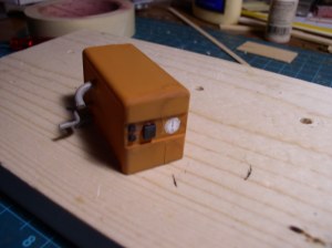
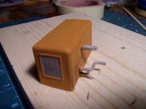
I’ve had to stay home from working in the railroad this week, but I did spend some time in the model shop.Calais Yard by itself is a rather simple affair, however there are a few pertinent details that help to identify it. A couple of posts back I mentioned the need to build a fuel oil supply tank car that was often seen in the yard. The location was next to the locomotive service tracks. Once the tank drain was connected, oil could flow from the car over to one of two service tracks. A large transfer pump did the work. It was painted orange and not hard to miss. My model of this pump is now complete except tor the attachment of hoses that were used to reach the locomotive fuel tanks.

OLYMPUS DIGITAL CAMERA

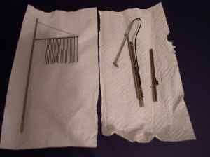
I’ll try to get it in better focus next time. There are also a couple of strange apparatus present in the yard. The taller device with the angular pipe is an adjustable sand filler that took dry sand from a pipe under the track and directed it to the sand hatches by a yard employee.

Nearby was a wood pole with a switchbox on it along with a hook over which a hose could be hung.The tall telltale warned a brakeman on a car roof of the Main Street Bridge. It was located adjacent to the engine house at the yard throat.

OLYMPUS DIGITAL CAMERA

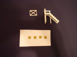
Finally there is a set of steps required between the freight house and the yard tracks plus a small black and yellow placard which served as a clearance warning to brake men riding car steps. Small things granted, but they are what set the scene as Calais Maine.

It will be nice to just open the box and place these various details when the time is right.

Ben

Mustard Seed Bins

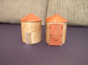
Here is a photo of the bins that lie between the siding and the building. They are used for storage of the seeds in between shipments from Saskatchewan. I’m not sure what the difference in the size variation in the doors mean. I will have to ask the next time I am in the area. Fortunately the company is still active, but it is the only holdover from the days of the railroad.

OLYMPUS DIGITAL CAMERA

Note that these are relatively short bins compared to grain silos.

Ben

May Update

It’s time I brought you, the faithful reader, up to date on my recent activities. Realizing the last time I wrote, I was preparing to plane down a yard full of ties, I’m sure you would like to see the results. Well, there aren’t any as yet. I’ve had some issues with my knees that have kept me from climbing up on the bench work to do the job. The actual planing part doesn’t take all that long, perhaps an hour and a half. The setup of the vacuum hose etc. takes a lot longer. I’m hopeful that a few sessions with physical therapy will help the knees and I can get back to regular things soon. In the meantime, I have been working in the model shop to try and carry on with alternative projects.

I have started another unique tank car which the MEC used for fuel oil delivery to locomotives that served the main line from Bangor to Calais and return. The usual layover for the BACA and CABA trains was Calais yard. So even though I am not modeling any of that 100 mile line, I will be having visiting RS3’s and GP9’s showing up in Calais Yard and Ayers Junction from time to time. There were two different tank cars that showed up from time to time. one of them is shown below.

MEC fuel oil Tank car

This is the model under construction now in the shop. I like the challenge of the platform, the maintenance style paint and the stenciled lettering.

I built the Eastport section house which will be near the yard throat. The photo shows the rough location. Eventually there will be a low rise in the terrain behind it.

OLYMPUS DIGITAL CAMERA

I have done some more rough siting of the Raye’s mustard mill. This location will be 3-4 feet in the background. I have added the mustard seed bins which I hope to show in my next posting.

OLYMPUS DIGITAL CAMERA

Details like the bins which are corrugated grain bins help to define the scene as being Eastport. Before I go much further with Raye’s, I hope to be there next month for a few more dimensional checks and detail photos. Raye’s is one of the very few structures that have survived from my era to the present. I’ll try to not be away as long until my next posting.

Ben

Serious Tie Reduction

In my last post I mentioned my little Makita power plane that I use for reducing the height of ties rather than sanding. There is nothing wrong with the sanding method except that it is slower. I have a whole yard full of ties and would just as soon speed up the process if possible. In this particular Eastport Yard the terrain is flat. The track is laid in gravel which trucks also use to gain access to the cars. In the later years that I am modeling tall grass has pretty much covered everything. This means that the ties are almost covered to the base of the rails. In the model the choice is to reduce the height of the ties before adding scenery materials.

OLYMPUS DIGITAL CAMERA

OLYMPUS DIGITAL CAMERA

In these two photos the plane has been placed on an angle to the line of the ties. It will be pushed directly along the tie line. This means that the cutting blade will be contacting about three ties at the same time. By doing this the impact of the blade hitting a tie is reduced significantly. This is assuming that I have adjusted the cut to be about 1/32 or less. By not skewing the approach of the plane, a depth of cut as much as 1/32 will tend to rip the tie away from the roadbed, so the practice of skewing allows a much more aggressive cut. My goal is to bring the ties to a constant height of about .050. Why didn’t I just start with 1/16 thick ties? For a couple of reasons; I like sugar pine ties that I can buy in bulk. Of course I can cut my own, but at this stage in life, I want to skip that step. Yes, there is a lot of chip waste, but the vacuum takes care of that quickly.

The planed ties are quite smooth and need some roughing up to make the remaining surface weathered and old looking. Once they are distressed, painting and staining will finish them prior to the rails going down. Every rail section needs a feeder connection to power. Once the rails and plates are in place they will also be painted and powdered. Because of the extensive grass cover, the amount of spikes and plates is substantially reduced, because they simply will not be seen..

I posted the planing method because it represents a different method for O Scale that I have not seen before. It certainly is not for everyone due to the initial cost of the plane, but I already had mine.While all of this preparation is going on, I have been experimenting with the siting of a couple of structures.

OLYMPUS DIGITAL CAMERA

The first is a section house that was located near the Eastport Yard throat. The second is the Raye’s Mustard mill.

OLYMPUS DIGITAL CAMERA

Not sure I like the position of this one yet. It may change when I add the grain bins.

Ben

Decrepit Track Modeling

One of the reasons that I chose to model the prototype Eastport Branch in the late 60’s was the rather deplorable condition of the track. Minimum maintenance if at all was the rule. Motive power was relatively light weight which yielded minimum stress on the track structure. Part of the accuracy that must be achieved in 1:48 constructing a working model is two fold, accurate enough to avoid derailments, and consistency in transferring power from the rails to the locomotive for smooth operation. If I were simply building a non-working diorama many of the problems would go away. My motive power was built some time ago and runs on DCC. They are also equipped with sound decoders. This means that each rail is electrically powered and that the rolling transfer of power to the locomotive is uninterrupted. These are challenges in and of themselves without making the track look shaky. In today’s rapid advancements, the ideal as I see it would be to use self contained, battery powered locomotives with no power at all on the track. One primary reason old track looks old is due to jointed rail, every 39′. Trying to kink 3 foot pieces of scale rail does not look the same. Battery power also eliminates the continuous contact problem. However, I simply have chosen not to get into another complex project of redeveloping my loco fleet into battery power.

One partial solution which is what I am using is to use scale 39′ rail sections but use R-O-W brass joiners and solder the assembly. This allows the slight kinking effect of short length rail pieces, but ties them together electrically and reduces the number of feeder wires needed.

OLYMPUS DIGITAL CAMERA

The photo shows what the track at Ayers Junction looks like today. The track curving to the right is the original ‘main’ to Bangor, 100 miles to the east. The track to the left is the Eastport Branch which no longer goes much farther than the photo. Although much of this original trackage was removed some years ago, the State of Maine chose to leave the section in place from Ayers to St. Croix Junction. One of the reasons to post this picture is to illustrate the strong influence that jointed rail has on the overall appearance.

Key Street Crossing Eastport

Eastport Yard during the era I have chosen looked like this photo. many of the ties were either buried to their tops or almost buried. The brakeman here is standing on Key Street at the south end of the yard.

1965 MaineCentral Eastport Yard

Shown here is the track which passed by Raye’s Mill and on up to the eastern warehouse which is the large building in the background. On my model this area is between two and three feet from a normal viewing situation. Much of the rail is hidden from a direct view and the tie plates are almost non-existent. At first it may look like the long grass would cause derailment and contact problems, but my own testing and examining the masterful achievement by Trevor Marshall in S Scale demonstrate the effect is achievable. All of this is a far cry from my previous clean and straight track with complete tie plates, spiking, and shaped ballast. It becomes obvious when comparing the two states that the new challenge is deciding just where the tie plates and spikes will actually show. I simply no longer need to install them everywhere and ballast is a thing of the past. One of the things that really helps here is the minimum flange depth requirement of P48 vs. the larger common flanges of NMRA O Scale. Road crossings especially can have prototypical flange clearances instead of the large unsightly gaps needed by oversized flanges. Once the initial track is all down I anticipate a lot of tweaking toward making things consistently operable. Hopefully this will clarify my goals in modeling the Eastport Branch.

The Power of Jigging

When it came time to start gluing down ties today, I was really pleased with the ease and speed of the process. The reason was a box full of pre-taped strips of ties that were mounted on masking tape. I filled this box while watching a movie on TV the other day, thanks to my spacing jig. Here is what it looks like.

OLYMPUS DIGITAL CAMERA

It is just a piece of pine board with a series of styrene strips glued to it. The original spacing was achieved by using a piece of flex track that I had on hand. To use I simply pick up a handful of ties and place them into the jig. Once the jig is loaded, I place a strip of masking tape across the ties and lift them out of the jig. It probably sounds a bit tedious, and it is, but watching a movie makes the time pass easily.

OLYMPUS DIGITAL CAMERA OLYMPUS DIGITAL CAMERA

It took about a little over an hour to lay all the ties seen in the photos. The turnout plates that have the paper templates are removable. Those ties will be laid individually as the turnouts are built on the work bench. For the glue I use yellow carpenter’s glue.

OLYMPUS DIGITAL CAMERA

It is applied quite liberally as shown and then each strip of ties is pushed down into the glue until the strip is flat. The ties end up being coated on the bottom and part way up the sides. In my case the almost abandoned track hardly shows the ties. The prototype is mostly buried in gravel and hidden in grass. The glue here needs to be very strong for the next step. Instead of the usual sanding to get the ties level, I reduce them to about half the original height. This is done using a small Makita powered plane that I have in my collection which is leftover from my boatbuilding days. It is about 3″ wide and can take about 1/32 at a pass. One caution even with the solid glued ties is that the planing process works best when the plane is skewed relative to the ties so that three or more ties are being cut at a time. Pushing the plane straight down the track line will occasionally rip out a tie or two if the cut is too aggressive. The sugar pine ties from R-O-W are easy to cut and the process raises a lot of shavings. It is best to keep a vacuum near by to remove the shavings as soon as practical.

The process described here may seem a bit crude to some readers, but I am not building a pristine mainline, only an old branch for which it is perfect. Next time maybe I’ll throw in a picture of the plane skewed in case this description wasn’t clear.

Ben

Eastport Roadbed

The laying of the Homabed roadbed for Eastport has been completed. I have plenty of material left over which I will use to fill in between the roadbed strips. Some of the filler has been installed which may make the actual roadbed layout a bit confusing. Look for the black track centerlines to confirm track location.

As indicated earlier, the reason for filling in between is that the yard trackage was buried in gravel up to the tie tops and a lot of it was hidden in grass overgrowth.

OLYMPUS DIGITAL CAMERA OLYMPUS DIGITAL CAMERA OLYMPUS DIGITAL CAMERA

As mentioned earlier the paper templates are glued on top of removable Homabed plates. This will allow the turnouts to be build in the shop where more comfort prevails.

OLYMPUS DIGITAL CAMERA

The large piece on the left in the above photo is the location of the Eastern Warehouse which will be built later. The lower track with the S curve is the spur down to the harbor.

OLYMPUS DIGITAL CAMERA

The layout of the harborside trackage along Sea Street is rather simple. From the turnout straight ahead is the siding that served American Can. The curved track leads out onto one of the piers served by the railroad.. This will probably be the steam ship pier. Originally there were two piers served by the railroad but in the latter years just one survived.

Tomorrow I hope to finish filling in between the roadbed and start laying ties. I have plenty of ties ready to go from the jig. The jig process saves a lot of time by preparing strips of ties about 14″ long ready to place into the glue. I did not show a photo of the jig because the method is quite well known, but if any reader wants to see it, just ask.

It has taken awhile to reach Eastport, but I’m pleased to have finally arrived.

Ben